Steam Engine September 2021


First attempt to design and build a miniature functional steam engine. Pictures top machining the crank shaft out of left over stock 50 x 20 x120 mm , cutting the crank pin to a diameter of 15 mm . Cutting the journals to 13 mm Diameter .


The crankshaft machined as can be seen in the left top picture. All oil passages drilled and where necessary the ends plugged and shown in center and right hand side picture.


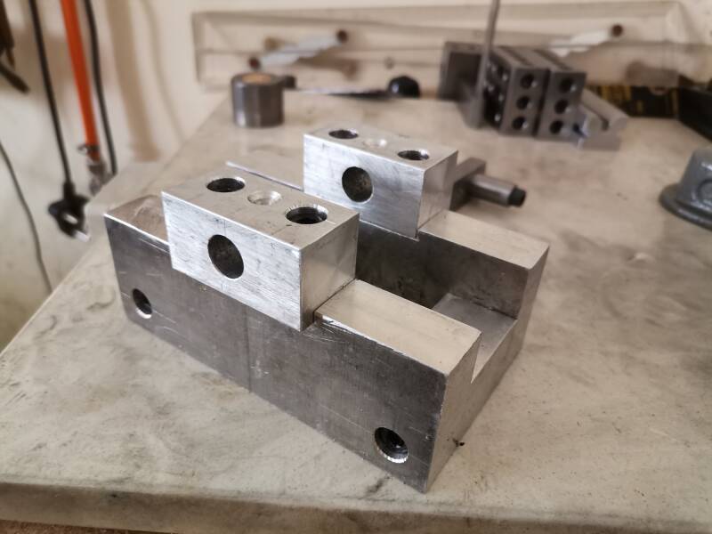
Center picture in the absents of castings I will be making the steam engine frame from aluminum all machined and bolted together.


Top pictures the base made in which the crankshaft will turn. Center picture slots milled in the top of the base where the bearings will be mounted.


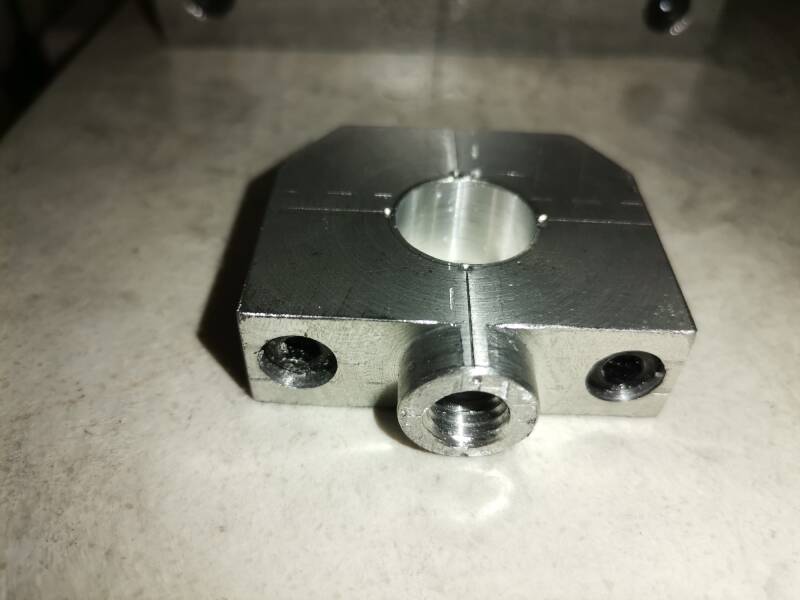
The bearing blocks made drilled and fitted , the bearing blocks were reamed to 13 mm diam with oil passages drilled
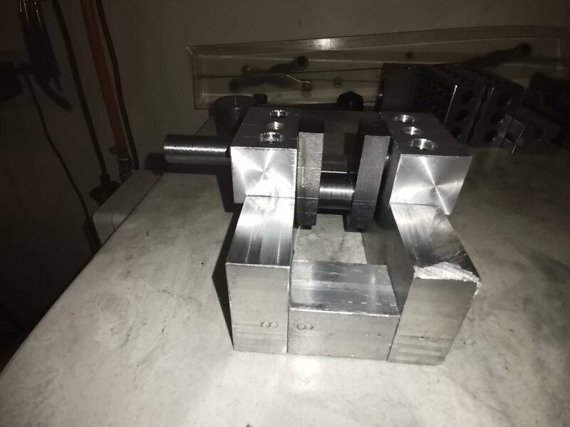

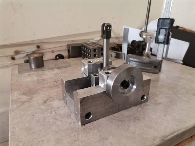
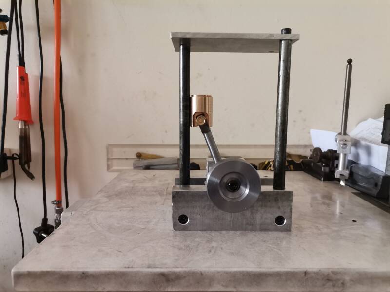
Crank shaft fitted and it is a nice fit in to the main frame. Center picture the big end of the con rod made, it is made a bit bigger overall , In case the aluminum as a bearing material fails. I can bore it out and fit bronze liners. Right hand picture the con rod big end fitted to the crank shaft and it is a nice running fit.

Picture left top the connecting rod made , picture center the one side of the bearing block machined down to 20 mm to make it sit flush with the main frame. Picture Right top in the process of making the cross head from bronze stock.
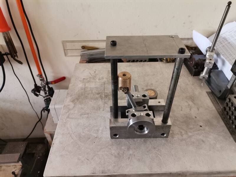
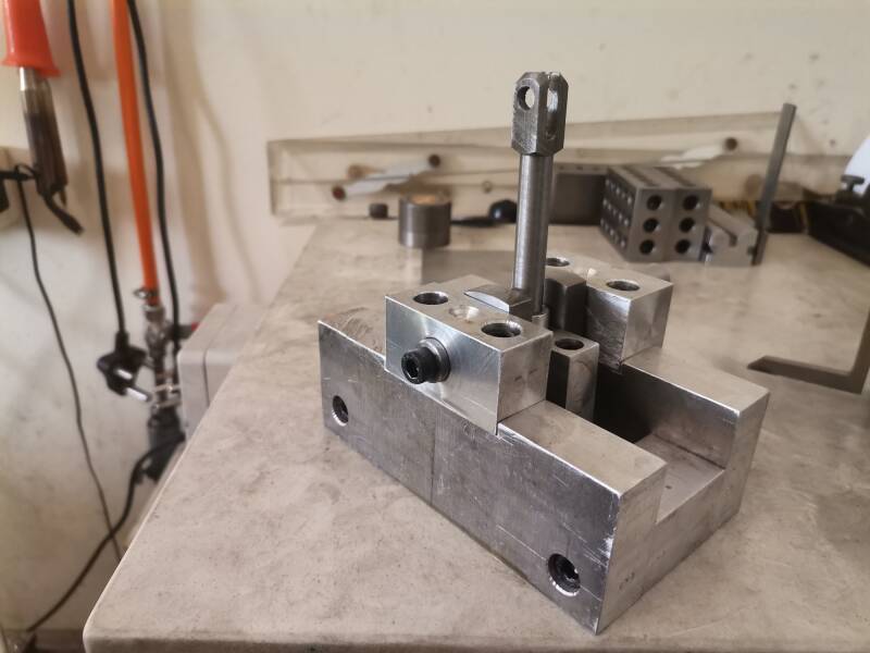
Picture top right flywheel made and fitted to the crankshaft. Center picture second side machined so it fits nicely over the con rod al we have to do next is drill a hole for the retaining bold. Picture top right hole drilled and tappet in the base for the three pillars . Also made the top cylinder base plate and temporary fitted.
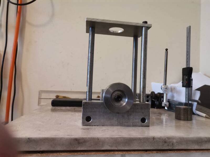

Different vieuws of the maine frame ,the hole machined that wil fit a tubular guide for the ctrss head.

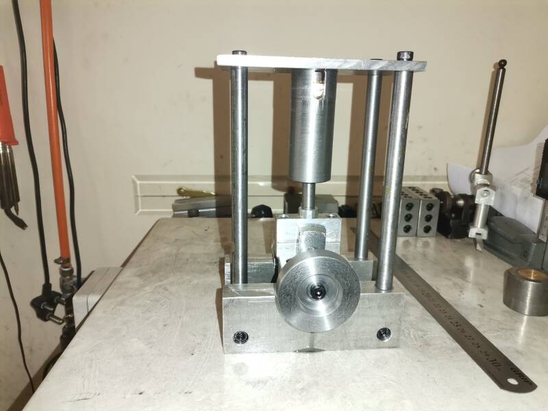
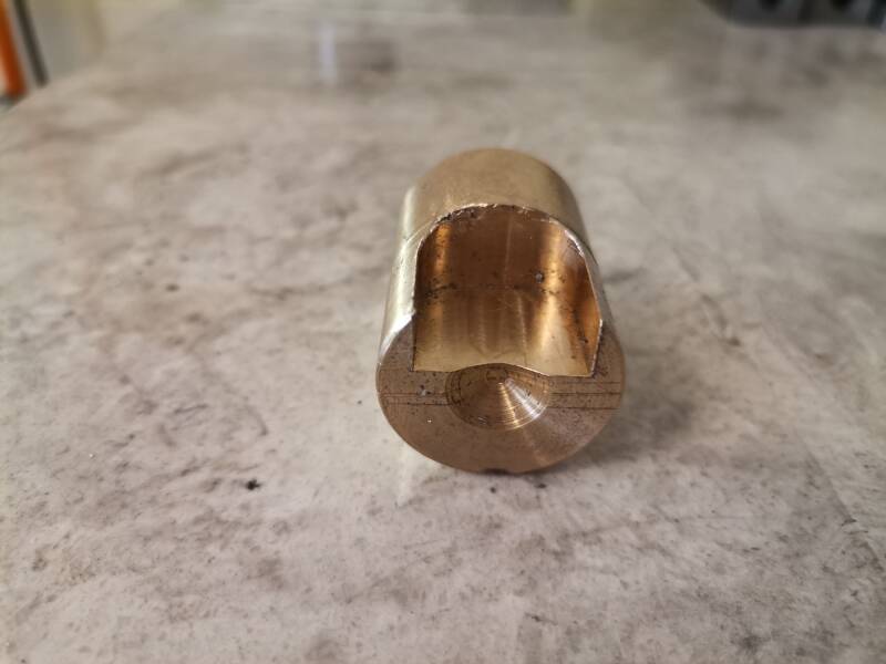
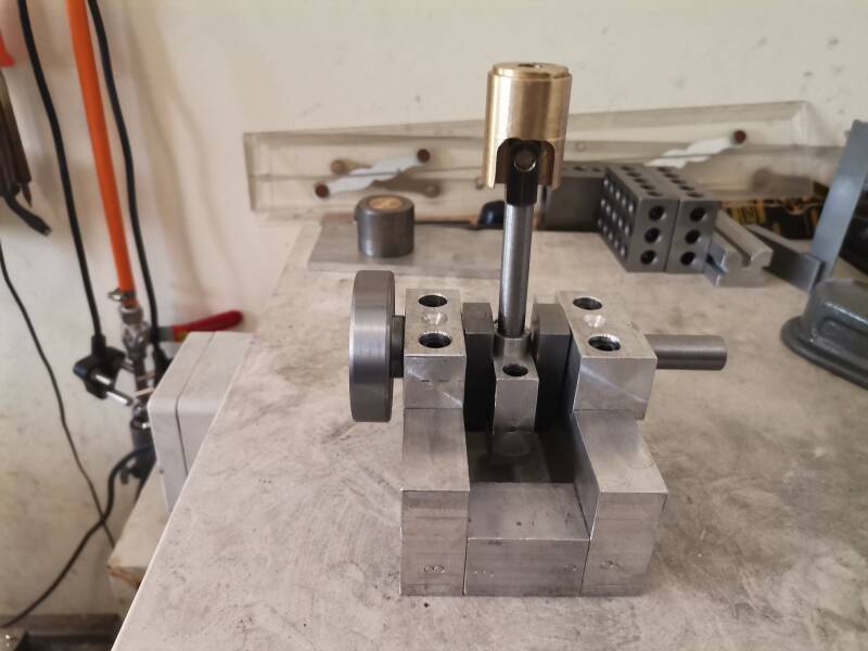
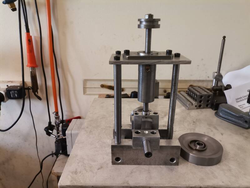
The tubular cross head guide being machined. Center top the cross head guide finished and fitted on the main frame it all lines up nicel and the cross head moves freely. Picture far right the piston made and the piston ringjust hope I will not break it when I fit the piston ring.


Left top picture machining the main flywheel tp athickness of 20 mm and a diameter of 90 mm. Center picture flywheel machined and fitted to te crankshaft. Top right picture cross hea securing plate made aand tomporary fitted.
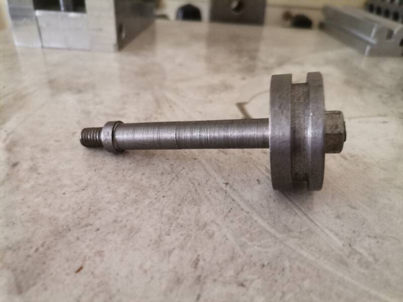

Piston rod made and fitted to the machine.


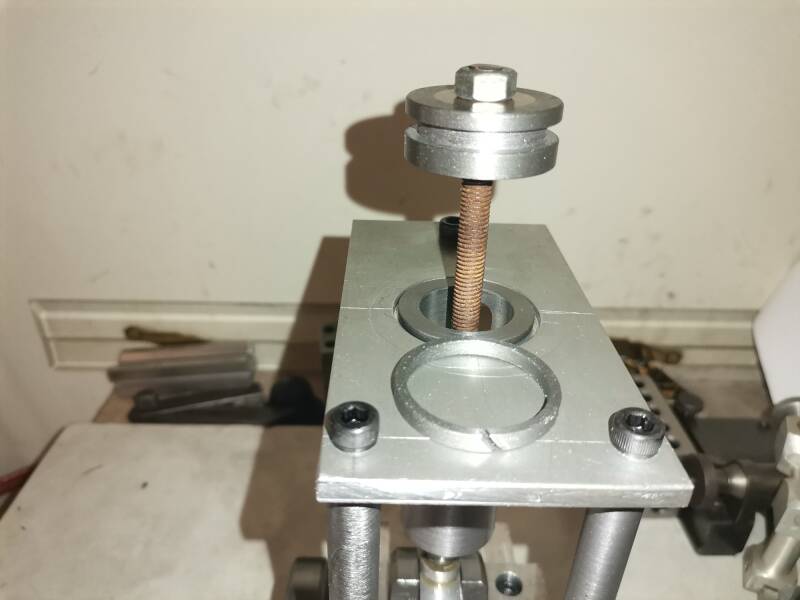
Bearing made and press fitted to cylinder bottom plate , center picture holes drilled in the flywheel to make it lighter. and I think more attractive. Picture top right the cylinder made and temporary fitted.


Left picture looking down on the cylinder fitted in position . Center picture the cylinder cover made , picture right top cover temporary fitted to the machine.


Alll holes drilled and tapped m5 in cylinder top and bottom ,secured with m5 x 20 mm allen cap srews.
Center picture trimmed top base plate to make room for the slide valve and make it look prittier at the same time.
Picture top right the inlet , outlet and exhaust ports drilled.


Making and fitting the valve chest for the steam valve.


Picture top left a rectangular nut made and fitted in the steam valve and a valve rod knuckle made and fitted.
Center picture cover made and fitted on valve chest, excentric and drive made and fitted ready to do the timing.


The engine is finally running on compressed air, and the compressor is having a hard time supplying enough compressed air to run it constantly.But in the end it turned out very nice , picture on the right after all the final touches
Create Your Own Website With JouwWeb