Home made milling attachment March 2023

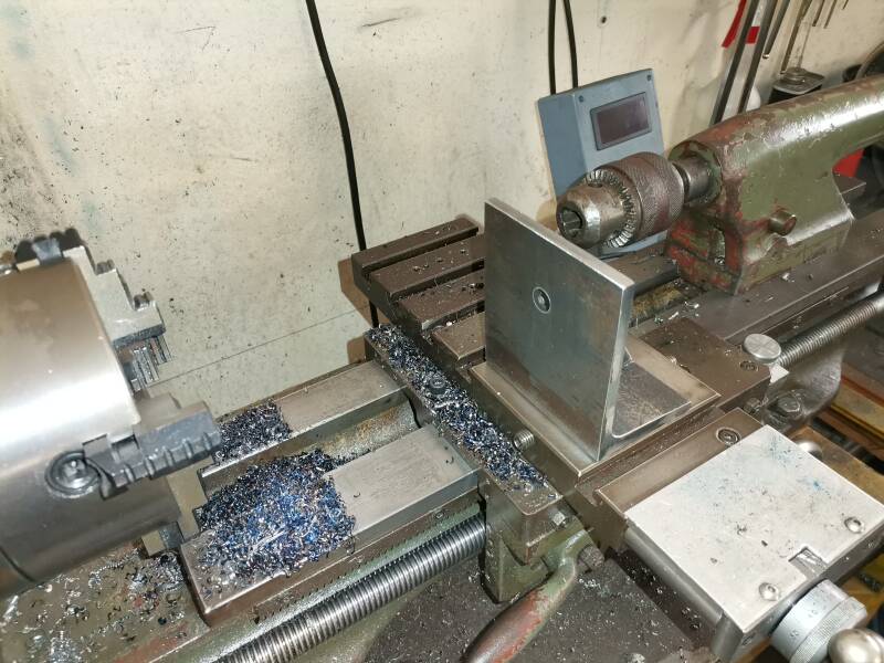

Support for the Milling attachment made.
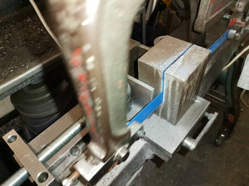

Base plate holding the milling attachment in position cut from a 70 x 70 x 100 mm block of steel , material left over from a previous job.
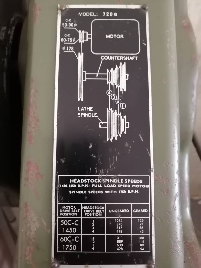
Taiwanese "ALLIED AMCO." 7 X 20 G ". Dec 2017.


This lathe was bought at scrap value, in it previous live it must have been dropped and many parts where either broken of or gone missing but its back in working order minus the gear train , so no cutting of any type of threads.
The lathe was build in Taiwan and looks like a Liberal "Myford" copy. This is all the information available at the moment. I also went on the internet but could not find anything. One thing must be for sure that more than one lathe was manufactured but that must have been before the internet so I expect that the machine was build in the fifties or earlier.
The one instruction plate Right hand side top is starting to make sense now and I believe it is connected to the tread gauge dial , explaining what number to engage , for which pitch. That is what I think as I have never seen that on any lathe..
Found a web site with Myford clones made in Taiwan. They where apparently produced by " Wey yii" . It has the same style name plate but , was sold as a " Colt " .
Amco allied 720 G specifications as measured.
720 G BENCH LATHE
Specifications
Distance between centers 508 mm, Swing over bed 177 mm.
Swing in the Gap 250 mm ,Swing over cross slide 75 mm.
Taper of spindle bore MT 2 ,Spindle bore 15.9 mm
Steps of spindle speeds 8 ,Range of spindle speeds 45 - 1283 rpm
Range of inch threads N/A (Due to broken or missing parts )
Range of metric threads N/A (Due to broken or missing parts )
Taper of tail stock quill MT2 ,220 V Motor 500 W ( bidirectional ).
Net weight +/_ 90 kg
Tread dial for the Amco lathe. 7 April,2021


Top pictures the fabrication of the missing tread dial for the Amco lathe. The body made from Aluminum 25 x 20 mm .


Body and gear blank cut to size , ready to measure the shaft size.
Center Picture a steel shaft made and pressed home 16 teeth gear cut with a # 7 cutter . Out side diameter of the gear is 16.17 mm OD, depth of the cut 2.2 mm.
Picture right hand top fitted to the machine and it seams to work great.
Gear train restoration attempt. Feb 2021.


Top left picture the lead screw removed from the machine and the and nut cut down by 25 mm, then a 25 mm long spacer made and fitted between end bracket and the end of the thread of the lead screw.
Center picture the lead screw machined down 25 mm to have the extra space on the lead screw om the head side.
Picture top right the lead screw fitted back to the machine.


Top pictures lead screw back in its space and the lead screw is coming past the head stock now by +/- 50 mm enough to fit two gear or one gear and a spacer for our attempt. The home made auto feed 220system made operational for the time being , while we do the rest of the planning..


Pictures taken from the back where the gear train just to be I am working out how to tackle the problem restoring it to some resemblance of its former glory.
Also as can be seen n the center picture there is a hole next to the spindle, apparently it is for a pulley lock assembly . This is accordingly to the ML 7 manual. This hole is 10 mm Diameter and 65 m/m deep.
Picture top right an old gear with a DP of 20 22 teeth that will mess with an other 26 teeth gear to form the reversing gears for the lead screw.


Picture on the left the two gears bored to 16 mm Diameter and will get bronze bushes.
Center picture cutting the Tumbler body on the old power hack saw.
Picture top right bronze bushes made for the tumbler gears and the holding bracket nearly cut to size.


Picture top left the bushes reamed to 10 mm diameter and it looks like the centers are lining up very nicely.
Center picture pins made and fitted and the gears mesh.


The tumbler assembled and fitted to the machine and it all seems to work out nicely I made a miss judgement with the operating lever . So will have to see to that. The rest of the change gears to be used on this lathe will be the same gears I will use on lathe # 1 , the necessary gears will be made up as we go along.
Picture top right the tumbler put trough its paces with the machine running I made some indentations on the side and in time will drill them deeper to make a solid positive position lock for the tumbler.


Picture top left the dimensions for the next person whom wants to tackle this job , If I had known any one with an Myford lathe I could have just copied every thing . But unfortunately I didn't , so this will help others if they would come across the same problem.


Pictures above the change gear carrier ( " Banjo " ) set out and machined from 12 mm aluminum. The Circular adjusting slot was done with the help of the home made turn table it works but it needs some fine tuning. Picture top right the gear s adjusting slot machined on the Mini Mill


Left top picture using the tapping jig tho tap the holes square to for a perfect fit of the spacer.
The Change gear carrier basically finished The slots are cut and the spacer fitted I hope that all will work out well.


Picture top left some key ways cut and the " Banjo " temporary fitted. The adjusting bold is been drilled right on the edge of the cast iron lathe housing and may not give me enough adjustment on the banjo but I will test it out as is.
Picture top right a sleeve made that will be keyed on to the lead screw.


Picture top left an other gear carrier shaft made with the T-nut fitted to the banjo.
Center picture bronze bush made for the Idler and picture top right flats machined on the idler shaft so it can be tightened to the banjo.


Picture top left keys made and fitted this is some sort of mock up. Center picture one of the many spacers in the progress of having a key way cut. Picture top right all the parts made and gears fitted two spacers still out standing.


Some changed where made to the banjo and a sliding guide was made to accommodate the changes to the banjo .


This is as far as we can go at the moment the only changes we will be able to make is when we make a complete set of gears to cut the full spectrum of treads available. The gears employed at the moment are A: 30 teeth B: 75 teeth C: 30 teeth and D: 110 teeth.
Additional changes made to the gear train , May 2021.


An other change made to the Banjo by cutting the top section , to enable to use smaller gears and become more versatile.
Center picture some changes made to the securing bolts and nuts to make changing gears easier.
Final gear train configuration Picture top right.A 30 teeth to an 60 teeth to an 75 teeth idled and than finally a 30 teeth on the lead screw this is supposed to give me 8 TPI , but something is wrong. All the gears used are home made.


More changes made to the gear train ,at the moment we have the following reduction : 28 to 60,30 to75 and 30 to 110.
Back gear cluster operating lever replacement. August 2021


Repairing the back gear cluster lever that engages the back gears on the head stock on my "Allied AMCO" lathe.
This lathe looks like a My-ford and feels like a My-ford , but is called an "ALLIED AMCO", I have not been able to find any information on it. I have searched the internet thoroughly.
The original back gear cluster lever was made of cast iron its replacement will be made out of out of welded and machined mild steel


Picture top left the back gear lever Machined to the correct size.
Picture top center the lever fitted after removing the chuck.
Picture on the top right all the holes drilled, shaped the catch installed , lever mounted on the machine and working like the original part but ten times stronger, not that it needs it. Lever has been secured with an M6 grub screw to the shaft
Cross slide spindle clean up. November 2021


Cross slide dismanteled and cleaned ready for a upgrade replacing the worn out spindle and spindel nut.
Center picture a new spndle nut in the making this nut is made of very fine grade cast iron.
Picture right top new cross slide spindle nut all holes drilled and fitted
Picture top far right new spindle made from m 10 ready bar and this worked out very well.
Oilers for the main spindle. November 2021


Finally made two oilers with caps for the main spindle to replace the grease niples that someone fitted in it previous live , after all the front bearing is a bronze taper bearing and I think is better served with some high grade oil.
Create Your Own Website With JouwWeb