"Ryobi" Drill press column up grade Oct 2020.


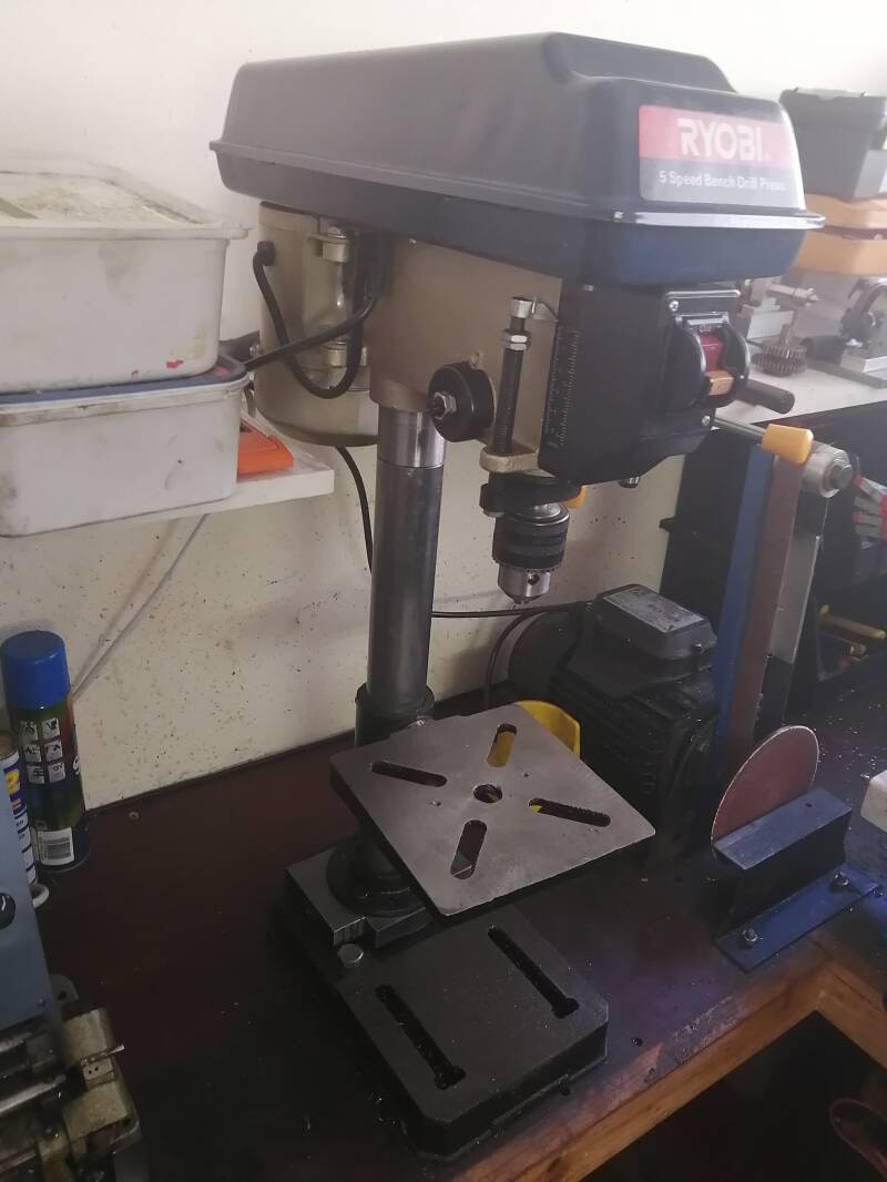
The Ryobi 13 mm drill press is nicely made and very functional in a small home work shop like mine. But the round main column is to flexible for the jobs I am using it on , the wall thickness of the column is 1.25 mm. Also the Drilling machine housing has a very sloppy fit on the column .For this reason ,I decided to beef up the column this also gives me an extra 90 mm in height. As we progress in this chapter bellow .


Left top picture the drilling machine and column removed from the base .
Center Picture a 20 mm spacer made between the column and the base , this is make up for the removal of part of the column that was deformed by the securing set screws in the body assembly.
Picture far right spacer and column temporary assembled and all fits nicely.


Left picture the extension in the lathe the side in the chuck fits nice and snugly in the drilling machine body ,the other side will be made to a press fit in to the column.
Center picture Both side machined and it fits very tight in to the original column .
Picture right hand side the extender pressed home all the way in to the column


left side picture column and table bolted back in position . One problem may arise at a later stage the center table can no longer be re moved from the column , simply because to give it a nice fit in the body the top of the column insert has a bigger O.D then the original O.D of the column.
center picture drill press body placed back on the column and secured with the original set screws.
Finally the right and side picture the complete machine all assembled and ready for action I gained 90 mm in height, original it was 260 mm between the chuck and the bottom table . After the alterations I now have 370.mm between the chuck and the lower table, plus the machine feels more solid , and not as flexible as before.
A few more alterations Jan 2021.
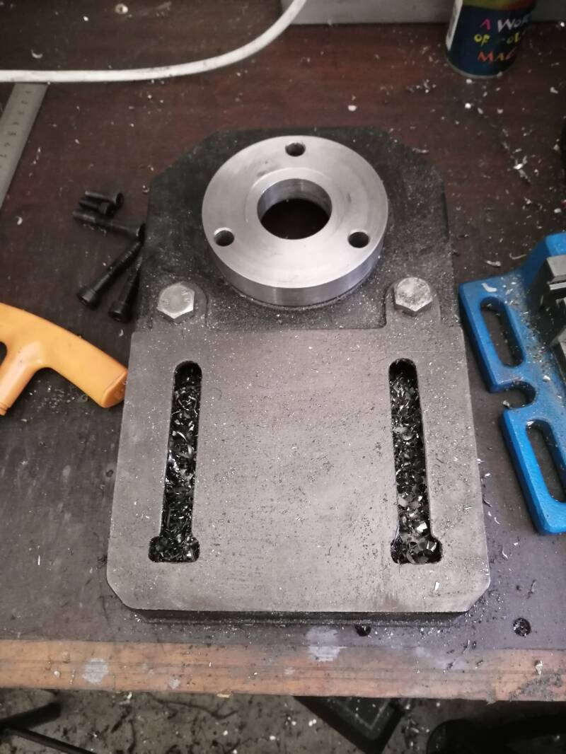


Picture top left the machine stripped and the original filler plate machined to a 100 mm Diameter ,20 mm thick.
Center picture a carrier plate made 100 x 150 x12 mm all holes drilled center hole tapped 10 mm, the securing hole in the lower table drilled ,counter sunk M6 ,using M6 x 20 mm hex head allen screws. This plate was made to give the column more lateral support.
Picture on far right a M 10 length of ready bolt screwed in to the carrier plate and locked in place with an M10 nut.

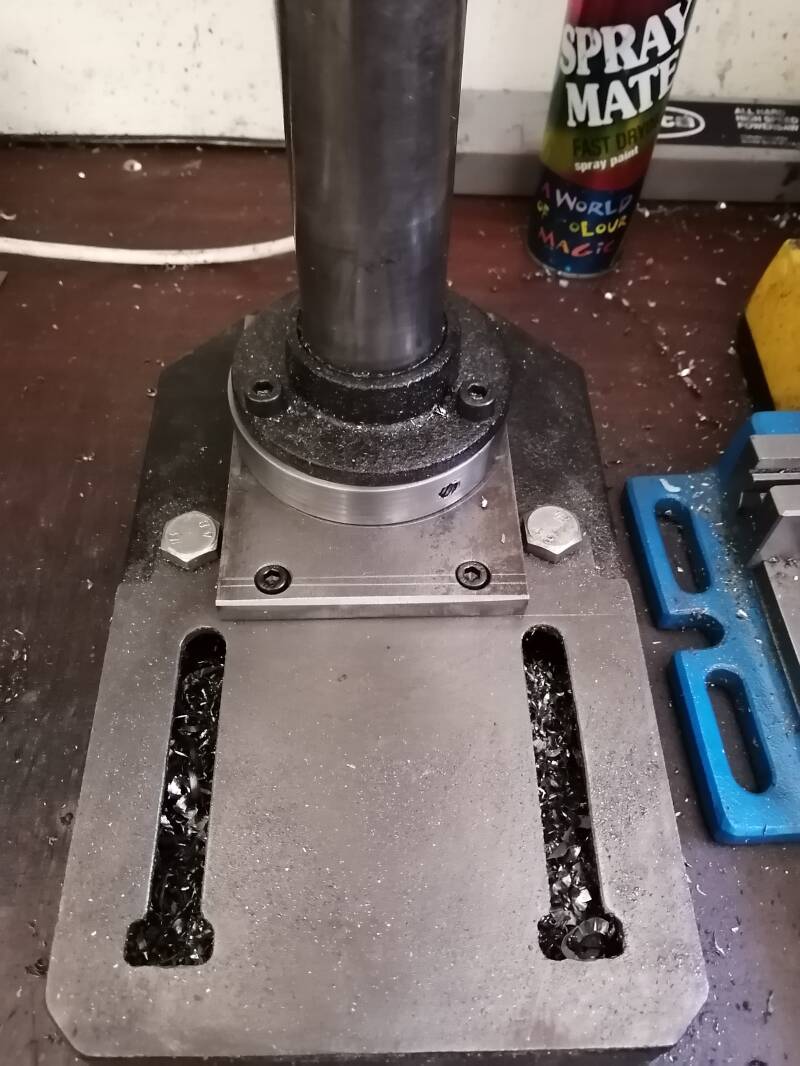

Left and center picture bottom section assembled all bolts secured.
Picture far right a cap made for the column and secured with a M 10 Nylock nut.

Machine assembled and ready to be used.
Create Your Own Website With JouwWeb