Doing some more work on the power hack saw December 2021


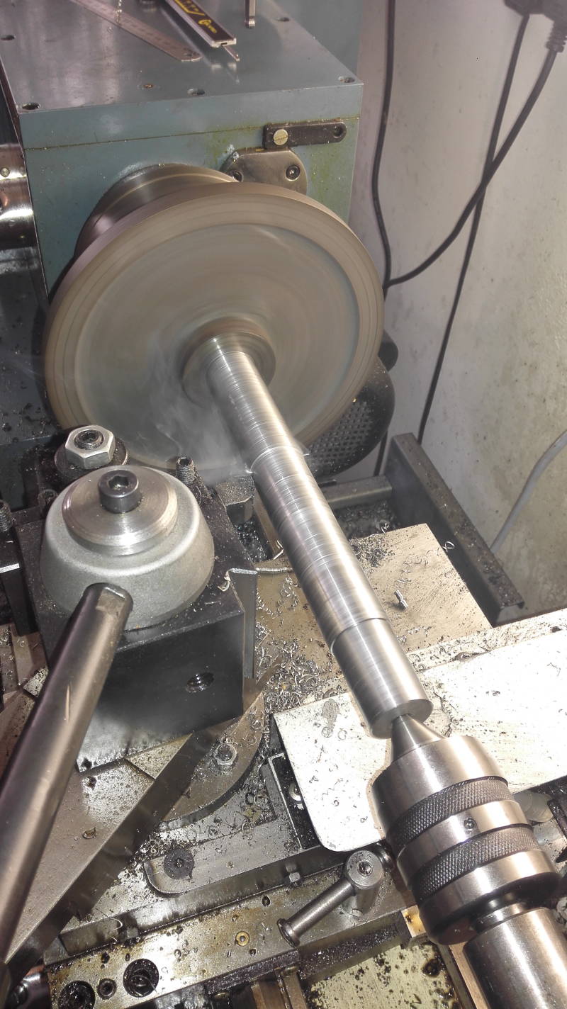
Stripped the power hack saw, to remedy some ailments that where overlooked last year. The pivoting slide carrier had so much slack that it was difficult make accurate cuts . The center picture the pivoting slide arm set up in the milling machine boring it out. Making it ready to press fit a steel sleeve in the pivoting slide carrier to bring to bring it back to spec. Picture top right turning a steel liner to be press fitted in to the re bored pivoting slide carrier .


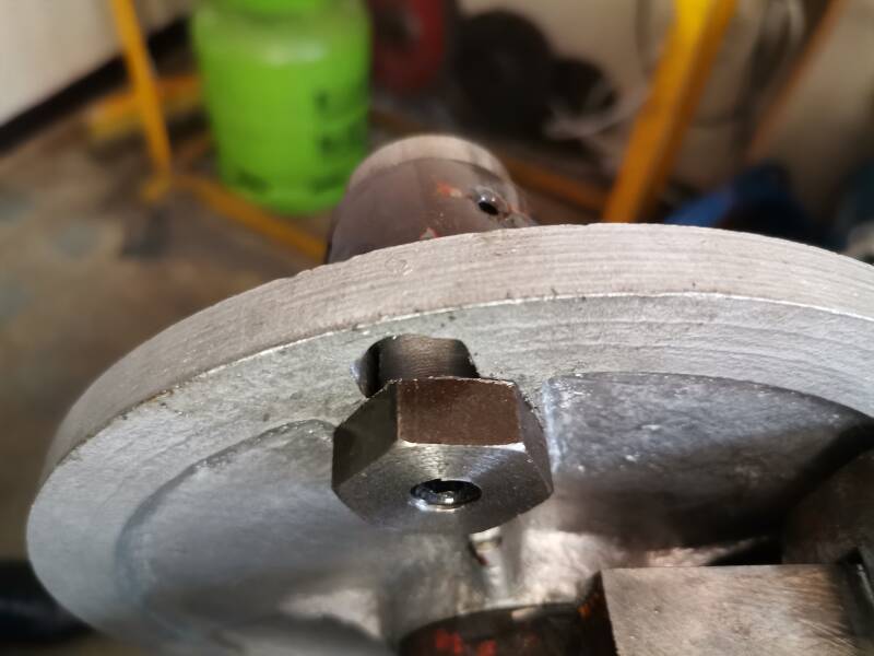
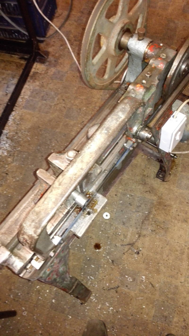
Left picture the sleeve machined to size and pressed in to the pivoting slide arm and a good fit it is. Center picture the pivot arm fitted back on to the machine and all the play is gone a very nice fit. Picture right top driving pin removed from the saw frame ,made shorter and made a end plate for it screwed down with a m 8 C/S Allen head screw.


Made new drive shaft pinion and fitted to the drive wheel all fits nice and clean and the machine operates very smoothly and the Pit man arm is nearly silent.
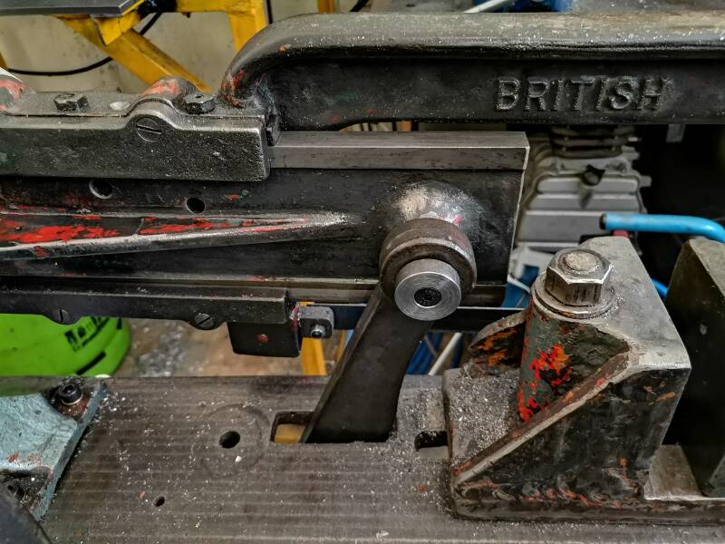
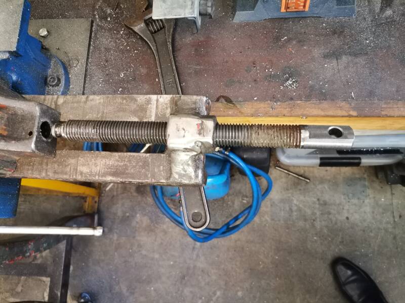
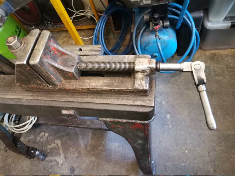
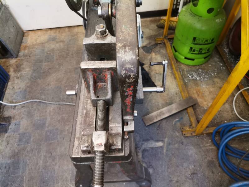
Made the saws limit stop more in line with new look of the machine and got rid of all the split pins. Center picture stripped the machine vice and cut of the cross bar that was always in the way of the saw frame , machined two flat sides to it to fit a proper swivelling handle to tighten the vice as shown in the top right hand picture.


I finally figured out that I have fitted the blade in the wrong position all the time. As can be seen on the picture I finally remedy's this .Center picture a limit stop made and fitted.
Cleaning and refurbishing power hack saw . Jan 2021.
Power Hack Saw 6" , New Economy 2 , Made in Britain.


Found those pictures on the web site of the "hobby machinist" asking for information and the origin of this machine a "New Economy 2" made in Britain, looking at the main pulley I think this machine was originally driven from an line shaft system It also seems to have a clutch of some sorts .So this specimen may be older than the one I am refurbishing. Al tough my machine has the hole drilled in the main body to have a clutch handle fitted.
Power Hack Saw 6" , New Economy 2 , Made in Britain.


New acquisition a Power hack saw with a lot of work to be done to it, I have a feeling that the machine was build in the late forties or early fifties when looking at the leg castings used on this machine. By the looks of it the machine has not seen a drop of oil for along time next step will be stripping the machine completely then cleaning it and repairing it , it may even get a coat of fresh paint . Pictures in middle and on the right stripped the machine to make it easy to transport.
Been looking on the net for the manufacturers data, so far with out any luck, I would love to know more about the factory that produced this machine and also properly date the machine.


I found some markings on the main frame, a casting mark 6HS1 and an other mark stamped in the frame top BEC 11288/62 where I have a feeling that 62 means build in 1962 or it could be 1862 ?


Picture on the top left the main part ready to be stripped and new parts to be made where it will be necessary.
Top center picture all the moving parts disassembled and in need of a good clean up it looks like a lot of parts have to be re manufactured and some changes will have to be made. The main drive shaft bearing has snapped and will have to be line bored and a new bronze bush made and pressed in to position. Also the main shaft is badly worn and needs to be replaced or Machined.
Picture top right stripping the base found the legs where not cracked but the center part section was broken and can be removed , an other job to be done as one can see an attempt of repairing by welding was made to one of the legs.


Picture on the left the broken legs supporting the power hacksaw . Center picture after removing the motor which is mounted on a home made base. Cleaned the name plate for more information. This could be the original motor. The company stopped to exist in the sixties , apparently the brass name plates where used between 1940 and 1960 while the company was started in 1892 in Rugby England according to "WIKI". The four bolts holding the motor base came loose this is where the problem and the course of the legs cracking and finally breaking started, this was due to the rocking motion created by the machine when in operation. Picture on the far right main bearing and pivot mount of the saw frame and the main bearing of the drive shaft . As shown on the right hand picture the part that carries the main slide has broken of and will have to be bored out and a bushed to make it operational again.


Pictures top left and center the vice that came with the power hacksaw , at one stage something must have gone horrible wrong , ripping the machine apart . I have cleaned up the vice ,filing the bottom of the vice straight so it can sit squarely on the main frame. It looks not very pretty but it will be functional. The holding plate for the movable yaw will be counter sank and an M10 Allen cap screw fitted. To make it possible to swing the vice on its pivot point. In order to cut under an angle without this bold head interfering with vices movement . As it has done up to this moment. Picture far right the vice assembled and greased up to make it fully operational.


Picture the top left legs trimmed cracked and broken pieces removed . 2 times 50 mm angel cut this will be bolted to the legs with m8 x 20 mm hex bolts as a support in place of the original cast iron base . Center picture the two angle brackets drilled and bolted 165 mm from the bottom of the legs, to the top of the angel iron. Picture top right two 38 x 15 mm washers made for the 5/8" x 3" UNC bolts that bolt the legs to the saw table.


Picture top left Standing on its own four leg very sturdy as rigidity as it was when originally designed and build. Picture in top center the original 5/8"x 6" bolt cleaned up and a 8mm x 60 mm steel washer made underneath the bolt head to cover the slot in the table. Picture on the right top the vice temporary bolted down on the saw table top.


Picture top left the main bearing mount in the process of being set on the milling machine for boring and re bushing.
Top center picture busy re boring main bearing mount to take a bronze bearing pressed in once finished.
Top right main bearing bored to size ready for bronze bush to be pressed in place.


Picture left top broken bolt drilled out and re tappet m8 to fit a guide. Top center cross brace cut and welded between the table legs.
Top right the slide assembled , a few holes drilled and counter sank so we can lubricate the slide while in motion, the Gib de burred and set up to take up the play in the slide some of the shims removed to take up the side ways slack it looks good and feels good.


Top left the crank set up in the lathe center being machined to clamp it in the three jaw chuck and machine the worn shaft down to 26 mm diameter. Center picture chucked up and machining the shaft down to 26 mm Diameter. Top right the main shaft one end machined down to 25 mm diam to take an taper lock of 25 mm diam and the pulley, the rest of the shaft machined down to 26 mm diam this cleaned up all the shafts wear and tear. The one thing left is to cut an key way in the shaft to accommodate the taper lock securing the 203mm cast iron pulley.


A 300 mm x 44 x 19 hollow bar phosphor bronze purchased to fabricate the center main bearing taking the crank shaft. left side picture all chucked up and machined the one side that will be pressed into the main frame ,and bored out to take the crank shaft . Picture far Right main bearing tested on the crank shaft.


Picture far left main bearing pressed in to the main bearing support, lubrication holes drilled in the Phosphor bronze main bearing. Center picture crank shaft and drive pulley assembled now we have to make a spacer, where originally there was some sort of clutch between main body and the pulley.Picture far right re tapped holes to M8 and main bearing bolted to the bed m8 X 30 Allen cap head screw and spring washers.


Picture far left saw main body fitted to the main bearing.
Center pictures crankshaft temporary fitted to the main bearing to come to the conclusion the I need two spacers one next to the crank pulley and one between the main bearing and the driving pulley I am puzzled how it could have functioned before i disassembled it.
Picture on the right spacer between driving pulley and the main bearing made next have to fit a 10 mm thick bronze spacer between main bearing and the crank pulley this is done as can be seen on the far right picture.


Picture top left brackets made to take the electric motor mounting. Center picture found a bit of 19 mm reinforcement bar they use in concrete construction machined it down to 17 mm round drilled and tappet M 8 hole on either side so it can be bolted between the two brackets on the machines legs. Picture far right made a motor mount for the electric motor, this will pivot around the holding shaft , the weight of the motor will hopefully give enough tension to the V belt and prevent it from slipping.


Picture on the left all assembled and test run but even with the smallest stroke the machine is dancing all over the floor , While doing 420 strokes per minute. I will have to get an taper lock for the 304 mm pulley this will slow it down to 285 strokes per minute , hopefully enough to be come a useful tool. Change of plan the original pulley from the electric motor has two groves the diameter is 102 mm. The one groove machined down to 60 mm diameter and a v belt groove machined next to the original , while the original diameter stays at 102 mm.
Picture on the right Made a bush for an imperial taper lock so it will fit on my 25 mm shaft all that needs to be done now is to cut a 8mm key way in the bush but also enlarge the key way on the shaft the pulley sizes are now 60 mm and 304 mm


Picture on the left cut a key way in the bush that fits in the pulley's taper lock. Center picture enlarged the key way in the crank shaft same size as taper lock and the bush shown in the left picture.
Picture far right two pulleys machined and pressed together to slow down the number of strokes on the power hacksaw made the shaft with an eccentric to be able to tighten the top belt the lower belt will be tightened by the motor weight . the two pulleys are running on ball bearings. The diameter of the big pulley is 165mm the small pulley is 70mm


Picture on the left a mock up of the secondary speed reduction pulleys on an eccentric . Center picture both belts fitted and the machine run up looks like I got the reduction right it sounds very cool, and is n0t dancing around the room any more. Picture far right the first cut completed a piece of 30 mm round stock cut nice and easy still using the original saw blade the machine came with, mission accomplished


Picture on the left a bronze spacer made between crank connecting rod and the crank , this makes the machine run much quieter . And finally the belt sizes are as follows primary belt 13 x 750 and secondary belt 10 x 1340 mm . There is a belt cover available but it has to be cut to size, this may or may not happen in the future.


Picture on the top left fitted four castors to the bottom of the frame , this makes it easy to move the machine around my small workshop.The castors each have a carrying capacity of 50 Kg the machine weights about 70 Kg . So I hope that this will be enough capacity to support the machine even when it is in use cutting steel. A bush made over the pivoting shaft for the motor so it stays lined up for the correct belt position.

A new vice made for the power easy saw , to make easy adjustments to saw different profiles.
This makes the power saw more user friendly.
Create Your Own Website With JouwWeb