Mini Mill v belt drive

Changing the mill from gear to belt drive October 2020, Completed 7 April 2021.

The first step has been taken a off-cut of 10 mm aluminum plate has been purchased. It is ready to be laid out and cut to the shape of the milling machine top and the motor mount.
Picture on the right with some persuasion the aluminum material was placed in the Power hack saw to reduce the size and roughly cut out the base and motor support mounting plate then to machine to the required shape on the milling machine.


Picture top left machining the general mounting plate square after cutting it roughly on the power hack saw.
Picture top center roughly cutting sides on the old power hack saw to fit the top of the mill ,after machining it square and to the required shape .
Picture top right base plate sides roughly cut to size , next step is the final machining and drilling of all the bolt holes and holes to fitting over the spindles. The aluminum mounting plate dimensions is 190 x 150 x 10 mm


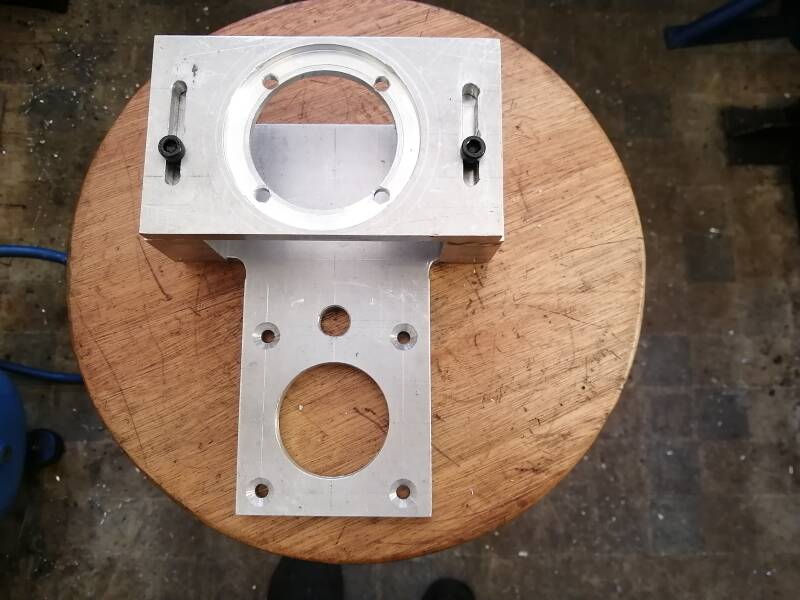
Picture top left the base plate machined all round to its final dimensions , it is now ready for setting out all the holes and proceed with drilling.
The next two pictures show some of the holes drilled and the risers cut to length they will have to be trimmed to he right height after the pulleys have been made and fitted.


Picture top left risers machined square all holes drilled and tapped and bolted to the base plate.
picture in center motor mount machined and guide hole drilled for slots
Picture on right motor mount machined and fitted on top of the risers.


Motor mount machined to take the motor base , holes drilled to secure the motor.
Center picture fabricating the driving pulley , this will fit on the motor shaft. It is made from 40 mm round aluminum the small pulley OD is 30 mm the bigger size pulley is 38 mm, the center hole is reamed to 10 mm ID. The total length is 42 mm.
Picture far rights motor pulley machined, except for the key way and the length can be adjusted once the driven pulley is completed and fitted.


Picture top left the main pulley in the lathe and being prepared and cut to the approximate seize while waiting for the v belts to arrive from the little machine shop in the US. OD of the pulleys 70 mm and 79 mm height 45 mm.


Picture top left a slot cut in the driven pulley for the main spindle lock also a recess machined in the main body to get clearance over the bottom of the shaft..
Center picture 4 mm key way cut in the driven pulley.
The 3mm key way cut in the motor pulley.


Finally after waiting patently for nearly three months the v belts have arrived , this was not the fault of the little machine shop in the USA, they where very prompt with full filling the order , but our post office locally is completely dysfunctional .I am going to need only one belt to do the conversion , but it makes me happier to have a spare.
Center picture adjustments made to the motor mounting plate extra holes drilled in the motor mounting plate to help with the cooling of the electric motor it sucks cooling air down from the top of the motor and expels air at the bottom. To help with this process I drilled 8 mm holes in the bottom of the mounting plate and cut the sides down with an angle of 30 degrees. I also drilled and tappet extra mounting holes , to get ample adjustment with the motor belt tension.
Picture top right base plate fitted and bolted down it is a snug fit.


Picture top left motor mounting plate fitted and bolted down.
Center picture the spindle pulley cut to the correct length, next step is fine tuning the groves for the V belt.
Picture top right after removing the plastic drive gear we mad an steel bush 16 mm OD 10 mm ID and 12 mm long . This bush was fitted in stead of the plastic gear and kept in place with an cir clip.


Top pictures the completed project including a safety shield over the belt drive.
Project completed 07 April 2021.
Create Your Own Website With JouwWeb