Hydraulic Press.
10 ton Hydraulic Press Frame


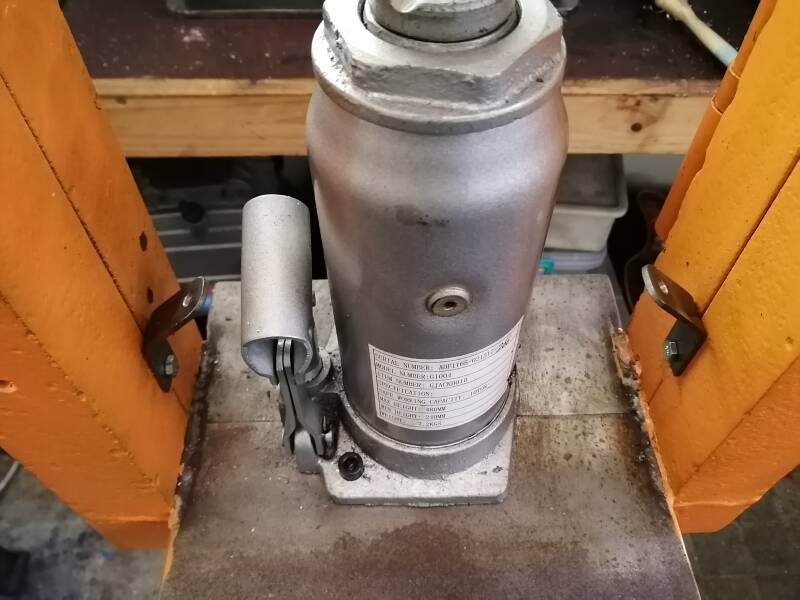
On the left the 10 ton jack purchased new, this equipment will be use in my new project . In the center some pitting that will be partly welded up , than the surface will be ground smooth. It is extra work but will be as strong as I intend it to be. The jack's maximum travel is 125 m/m as per instructions supplied


Pictures on the left and center, the up rights cut out and tacked in position. The dimensions of the uprights are as follows 4 pieces of 50x50x6 m/m angle welded edge to edge the length is 440 m
Right top picture the table for the jack to be secured on, has been tacked into position consisting of bright mild steel flat 2 pieces of 250x100x10 m/m welded edge to edge.
For the top section I used 350x120x25 m/m bright mild steel flat.
The next step will to weld it all together, clean up and paint.


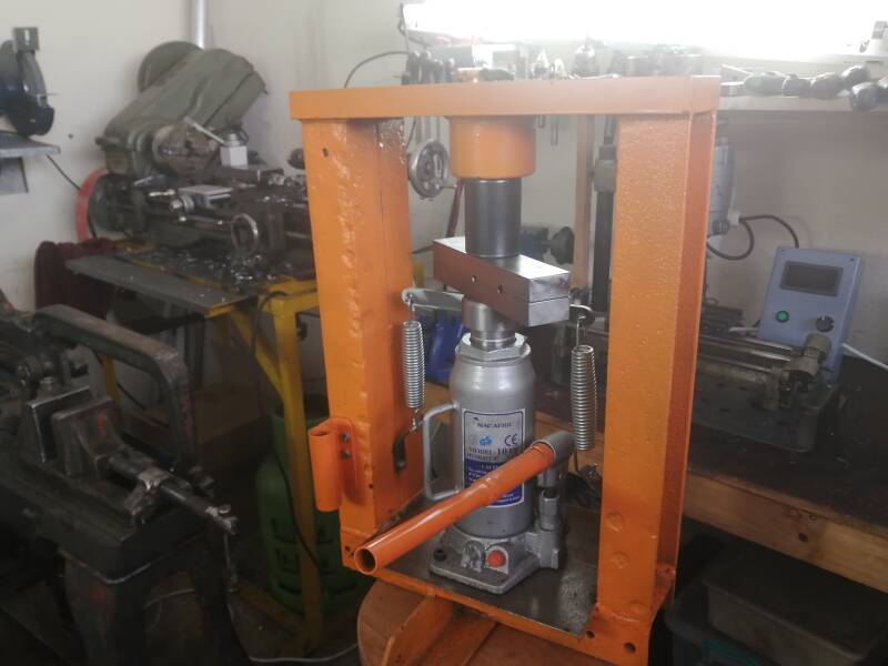
An other step closer to completion on the left testing the rigidity of the frame, it stood up well to the test.
In the center made a center hub for the top of the press. Welded in to position. I will use this hub to finally centralize the jack. The hub is made from bright mild steel 75 m/m diameter and a height of 50 m/m a 19m/m hole is drilled in the center.
Picture on the Top right . At the moment the jack has an travel of 145 m/m this is 20 m/m more than the specks supplied with the jack I will make a cap over the top of the jack to rectify this problem. The cap will be made from 60 m/m round stock.


Top left cleaned up and spray painted out of an aerosol can. The dimensions of the center hub are Diameter 75 m/m bright mild steel stock length 50 m/m with an 19 m/m hole drilled in the center. If the need arise I can at an later stage drill a 19 m/m hole in the top bar.
Picture in the center, the cap on the top of the jack in the process of being machined to size.
Picture on the top right the cap machined down to the final dimensions
Next is to drill and tap two 8 m/m mounting holes in the jacks base plate.
Picture lower left the jack placed in position to have the mounting M 8 holes marked and drilled. The maximum travel of the ram is down to 125 m/m as per instructions supplied.
Center below made a swage block that can be used on this press and is ready to be tested.
Picture on the right the completed product with some alterations done to operating handle. Also provided a safe storage for the operating handle out of the way.


Press operational


Finally completed my hydraulic press in the picture top left made two brackets drilled mounting holes and fitted brackets to the press frame.
Picture top center milled a 6 mm slot in the top cap of the jack and fitted a 20 x 6 flat bar in this slot , hole drilled at the ends to take the springs.
picture top right all assembled and tested working as expected, the total travel of the ram is 110 mm.


Pictures top left removable Drifts made with a length of 70 mm and the smaller 35 mm , for fitting in the hydraulic press. Made from some scrap metal laying around this will make using the press so much easier when handling shorter work pieces.


Picture above made an extension to the right side of the frame to stabilize it when using it at full pressure , a 150 x 50x 50 mm x 6 mm angel welded to the frame. Also made an knob for activating or releasing pressure when operating the press. September 2020


Left picture made a rack for the removable Drifts, this was welded to the main frame.
Right side picture the removable Drifts stored in there right full position.
The two Drifts cleaned up and ready for action.
Create Your Own Website With JouwWeb