Making of a simple Home Made Anvil from angel iron.

Anvil made from four left over 80 x 10 M/M angle iron 200 M/M long and all welded together.This gives it a solid 40 M/M center core
The next step is going to be the horn , which I will machine from 50 M/M Round stock and welding it to the frame. As can be seen on the lower middle picture. Then a clean up, and paint job to finish it off.


Stand for the home made anvil. Fabricated from a piece of two and a half inch galvanised pipe the three legs made of left over one inch black pipe. the base for the anvil to be bolted on to, will be made of two pieces of 90 X 10 M/M ftat M.S. welded together to form a platform of 180 X 190 M/M X 10 M/M. The Anvil can then be bolted down with four M10 bolts. And will andbe ready to receive some serious hammer blows in my DIY workshop..


After using the anvil on several occasions I found that it needed a bit more body to give it a real solid feel when you strike it with an hammer. So I bought some bright mild steel flat bar 150x190x25 m/m and welded it all round in such a way that I created a little 90 degree step, set back from the horn. Now a touch up paint job and we will try it out again.

Home made Disk/Belt sander.

A disk sander for which I enrolled and a 220 v single face motor of a swimming pool pump that run dry and destroyed the pump . But kept the motor in good health . Than some left over steel from a automatic gate closer welded together to make the motor mounting bracket, picture on the right.


Picture on the left one of the old sprocket from the automatic gate closer machined down to 150 M/M diameter. The center drilled out and tapped to M10, a perfect fit on the motor shaft. Purchased a packet of 150 M/M grid 40 sanding disk, I will have to glue them on or get a sheet of Velcro, glue that on to the steel disk and have a easy way of fitting and removing the sanding disk.


On the left all the parts are assembled and nearly ready for use. The only thing still missing is a guard over the sanding wheel.
On the right a guard and the on/off switch which started life as the emergency stop for a lift motor. This has all been made up and fitted. I made the guard oversize in case I want to increase the disk size later.
NB the gaurd was removed as it intervened with the sander function and was redeployed on lathe # 2


A small addition to the sander, the intention is to also run a 25 m/m belt from the same shaft the disk is mounted on. the extension is part of the swing arm of a electric gate cut to the right dimensions. With slots cut in this arm to make belt changing or adjusting the belt tension easy.
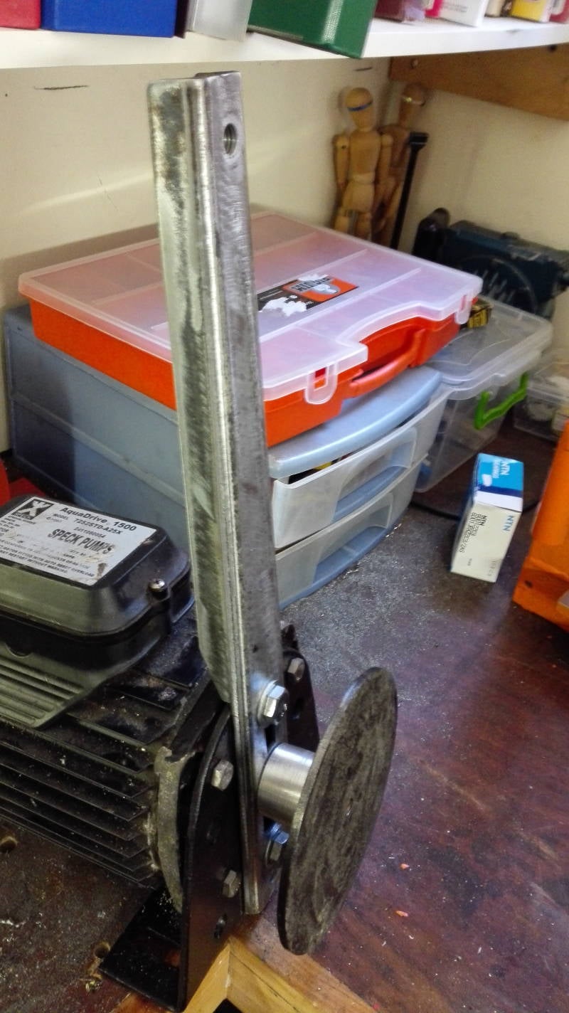
Picture on the right using my 7.5 ton home made Hydraulic press to tool holder press fit the drive roller on to the Disk hub.


Picture on the left my roller press fitted to the drive shaft. Picture on the right the mounting plate and carrier arm fitted with a small alteration I had the turn it around and machine the sides down to make it fit properly. Picture Bottom left , the top roller made and bearings fitted. right hand bottom picture roller fitted on to the arm. Right hand bottom almost completely assembled and test run. Just a matter of bolting it back in position.


Picture on the left all assembled and up and running . Next step is to try, finding belts of 50 m/m X 762 m/m at the moment I am using belts of 25 m/m X 762.m/m made for an Ryobi disk/belt sanding machine.
Right side picture a support made from aluminum angle was fitted to assist with the grinding. I will cut the angle aluminum to the right width when I find the right size belts.

Alterations to the Hobby craft drilling , milling machine.

Strengthening the cheap Chinese drilling machine , in to a more sturdy machine tool . On the left the bright mild steel bought for the project and the stripped down drilling machine.
On the right all the parts machined and holes drilled and tapped next step getting all the cap screws and assembling. Bellow left I fitted a solid bar inside the main holding tube to strengthen it. Below right i drilled and tapped four holes to hold a mini max 2" vice for small milling jobs. picture below all the parts assembled and ready for testing


New tool post for the lathe.

Not being able to use a boring bar , because the travel was not enough I decided to make some changes and made a new tool post from some scrap steel and I am reasonably happy with the result. This may not be the final solution, but will do until I decide to make a more complicated contraption

Home made automatic feed for my second hand Taiwanese Lathe.

After looking at newspaper adverts to buy a second hand lathe , for a long time , an advert caught my eye. I could not believe the price they where selling the machine for . Got in to my car bought it , I asked nicely to help me load it in to the car, and took it home. the previous owner attempted to restore it . But not very success full, but I saw the potential in restoring it .
When I bought it the gearbox was broken and the gears driving the gearbox where also missing or stripped.I cut up the gearbox housing but kept the longitudinal feed shaft bearing supports. And refitted this to the back of the cut down gearbox housing that I kept, and made a handle for this so I could use the shaft for feeding the saddle but it didn't gave me the finish I desired.


I found a couple of automatic gate openers with a 12v motor geared motors.
On stripping the automatic gate openers .I cut of a couple of the sprockets, modified them and made a gear train , and still have chain plus sprocket available for spares.

Then cutting down the original mounting brackets I made use of this and used it on my installation.
On testing the longitudinal feed I found it worked fine but there was a lot of slack in the chain.
This looked terrible so I made a tension device for the drive chain out of left over bits and pieces from the original Automatic gate drive mechanism.
I could have made a switch for the drive to change the turning direction but decided against this . But kept my options open in-case I change my mind at a later stage.
The next step will be to make a guard over the exposed gear and chain when the mood strikes me.
All this is driven from a 12 v DC battery charger that has been collecting dust on one of my shelf's for years.

On testing the longitudinal feed I found it worked fine but there was a lot of slack in the chain.
This looked terrible so I made a tension device for the drive chain out of left over bits and pieces from the original Automatic gate drive mechanism.
Also these motors are not designed for continuous use, and get pretty hot after a while , so this will also need a re think.
The next step will be to make a guard over the exposed gear and chain when the mood strikes me.


Picture above right hand top, made an shelf to the outside of the lathe stand , this can be utilized when using a magnetic clock gauge base.
Picture on the left made a cover plate over the bed of the lathe trying to prevent a lot of the swarf collecting in this area . The swarf are the cause of a lot of wear and tear.
Create Your Own Website With JouwWeb